1.0 Introduction
To efficiently render a scene, the minimal possible amount of geometry must be passed to the GPU. Objects that do not intersect the view frustum can be ignored. When rendering using an additive shadow algorithm (stencil shadow volumes or shadow mapping), the scene is rendered in multiple passes, one pass for each light source. In this case objects can be ignored when they do not intersect both the view frustum and the light source's bounding volume.
For shadow casters though, checking only against the view frustum is not sufficient. Objects that lie outside the view frustum (herein "the frustum") can still cast shadows into the visible area. Diagram 1 shows a simple case.

Diagram 1: B lies outside of the frustum, yet it casts a shadow into the frustum
If instead, the light source's bounding volume is used to determine potential shadow casters, then all correct shadow casters will be returned. But this approach is too conservative. It will also return true for objects that cannot cast a shadow into the frustum. The final results on the screen will look the same, but it will take longer to render as all the vertex calculations must be performed. Diagram 2 shows such a case.
Diagram 2: C intersects the light's bounding volume, yet it cannot cast a shadow into the frustum
To solve this problem, we instead check against a shadow caster volume. The shadow caster volume is the convex polyhedron that intersects any objects that can cast a shadow into the view frustum. It is calculated by extending the view frustum to include the light source. Diagram 3 shows the shadow caster volume for the scene in Diagram 2.
Diagram 3: The shadow caster volume for the light source includes B, but not C
Note that as well as checking potential shadow casters against the shadow caster volume, they should also be tested against the light source's bounding volume. This is particularly important for small point light sources.
For a description of how a convex polyhedron (frustum or shadow caster volume) is used with scene management data structures like an octree or a BSP tree, see [LENG02a].This article will cover the calculation of shadow caster volumes, and in the process of doing this, will also cover LUP decomposition of matrices. LUP decomposition turns out to be necessary for the numerical stability of this algorithm, even when using double precision IEEE 754 calculations.
The way the shadow caster volume is generated depends on the type of the light source. To start with we will cover point lights, then later directional lights. Finally, the special case of shadow caster volumes for semi-transparent objects is discussed.
2.0 Point Light Sources
For the purpose of this article, we will assume that the frustum is stored as a set of planes. Where the frustum volume is the intersection of the plane's positive half spaces. This means that each plane's normal points inwards as shown below.

Diagram 4: View frustum plane normals point inwards
For a point light source, when the light lies within the frustum, the shadow caster volume is the same as the frustum.
When the light lies outside of the frustum, the frustum must be extended to include the light. We create a new polyhedron, using all the frustum planes that the light source lies on the positive side of, and creating new planes for each edge that is shared by one plane that points towards the light and one that points away.

Diagram 5: Shadow volume planes. Unused frustum planes also shown in light red.
But the devil is in the details. Firstly we need to be able to calculate the edges of the frustum, then we need to ensure the normals of the new planes point inwards, not outwards.
If we know that the view frustum is always a simple six plane pyramidal frustum, then we can use the known view space edges, and transform them into world space. But to handle more general cases (such as the frustums formed by portal clipping, or the bounding volumes of semi-transparent objects discussed below) we treat the frustum as a convex polyhedron.
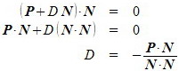
To find the edges of a convex polyhedron, we first need to find the vertices of the polyhedron. Finding the vertices involves checking all three plane combinations to see if they intersect at a point, then checking that the point is on the polyhedron's surface. We define a plane P as a unit length normal vector N and a scalar distance D to the origin.
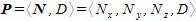
D is the signed distance from the plane to the origin in the direction of N .
The signed distance from a plane P to a point Q in the direction of N is,

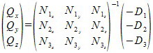
A point Q lies on a plane if Q ? N + D = 0. So to find the intersection of three planes, we need to solve a system of three linear equations,

In matrix form,

There is not necessarily a solution to this system of equations, and neither is there necessarily only one solution if they are solvable. But we are only interested in the case of three planes intersecting at a single point, and this corresponds to the case where there is a single solution to the system of equations.
The method that most people are probably familiar with for solving such a system of equations, is to multiply both sides by the matrix inverse like so,
While mathematically correct for real numbers, this unfortunately gives inaccurate results when using floating point numbers. If we do not solve this system of equations accurately, then for a valid polyhedron vertex, we are liable to discard it as may end up on the negative side of a plane. A much better way to solve the equations is LUP decomposition (also known as LU decomposition) [CLRS01] , [PTVF88].
2.1 LUP Decomposition
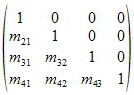
The basic idea of LUP decomposition, is that given a non-singular (invertible) square matrix M , we want to find matrices L , U and P such that,

Where L is unit lower triangular, U is upper triangular and P is a permutation matrix. A lower triangular matrix has all entries above the main diagonal 0, and an upper triangular matrix has all entries below the main diagonal 0. A unit lower or upper triangular matrix is lower or upper triangular with all entries on the main diagonal equal to 1. For example, a unit lower triangular matrix,
and an upper triangular matrix,

A permutation matrix has one entry per row that is equal to 1, and the rest equal to 0. When pre-multiplying a matrix M with a permutation matrix P , the rows of M are swapped. For example,

We want to find L and U to allow us to solve the system by using backwards, then forwards substitution. Given a system of equations in upper triangular form, we can solve using backwards substitution as follows,
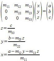
And forwards substitution with a lower triangular works the same way, only we start from the first row of the matrix, not the last. With a unit lower triangular matrix, we know the entries main diagonal are 1, so it's even simpler,

Once L , U and P are found (and they always exist for non-singular square matrices, though they may not be unique), it becomes very simple to solve MV = C .

Let Y = UV and solve LY = PC for Y using forward substitution. Then solve UV = Y for V using backward substitution.
So now we need to find L , U and P . This is done using Crout's method .
First we'll look at the simpler case of LU decomposition (no permutation matrix).
Let M be an invertible nxn matrix.
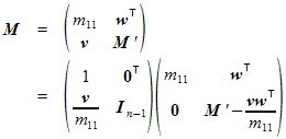
Where
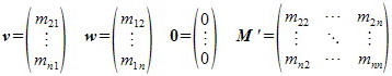
and

is called the Schur complement of M with respect to m11. If M is invertible, then so is the Schur complement (see [CLRS01] for proof). This then gives us a recursive way to find the LU decomposition. Let L ' U ' equal the Schur complement, where L' is unit lower triangular and U' is upper triangular. Then we have,
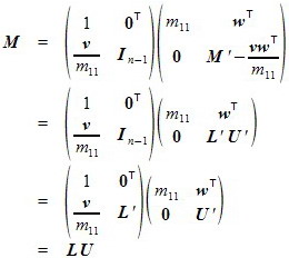
To implement this algorithm, the tail recursion of decomposing the Schur complement into L ' U ' can be converted into iteration.
The LU decomposition will fail if there exists i in {1,..., n } such that mii = 0. Even if no such i exists, the LU decomposition will still have numerical stability problems if any mii is a very small value.
LUP decomposition permutes the matrix so that at every step we are dividing by the largest possible value. This additional step of finding the best (largest) value and swapping rows appropriately, is known as pivoting. If no non-zero value is found in the first column of any Schur complement, then the matrix M is not invertible.
Listing 3 implements LUP decomposition, and using the decomposition to solve systems of linear equations. The permutation matrix P is stored as a permutation array, since this is a more compact representation for exactly the same information.
2.2 Calculating the New Shadow Caster Volume Planes
Now that we have the points of intersection of the planes, we need to test if they are near the polyhedron, and are therefore vertices of the polyhedron. To check if a point lies in or on the polyhedron, we find the distance from each plane to the point. We say the point lies in or on the polyhedron if every distance is greater than some very small negative value. Note that in Listing 2, this "small negative value" is not a constant, but proportional to the plane's distance from the origin. This is because of the cancellation that occurs when subtracting two floating point numbers that are similar in value [GOLD91] .
From the vertices, we need to determine the edges of the polyhedron, where an edge is simply a pair of vertices. To do this, we loop through each pair of vertices, and if the vertices share two common planes, then we output an edge. Notice that this requires us to store the plane indices with each calculated vertex.
Now that we have a method for finding the edges of a polyhedron, we return to the problem of constructing the new planes needed for the shadow caster volume.
Given three distinct points we can construct a plane as follows. First we need to calculate the plane's normal. For this we use a cross product, but to get the direction correct, we need to impose a winding order on the points. For a clockwise winding order of points P1, P2 and P3, the normal can be calculated as follows,

Now we have reduced the problem to calculating the plane given the normal N and a point P on the plane. So we need to calculate D, the distance to the origin.
Let Q be the point on the plane closest to the origin, so

And since Q lies on the plane,

Substituting for Q ,
So given three distinct points with clockwise winding order, the plane they form is
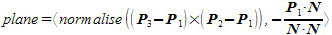
To form a new shadow caster volume plane, we have three points, the two silhouette edge endpoints, and the point light source's location, but we do not have a defined winding order. So to calculate the plane, we use the above method for three points, then flip the direction of the normal if necessary. We use a point known to be within the frustum to test if the normal needs to be flipped. If the signed distance from the plane to the point is negative, then the normal is pointing in the wrong direction. A simple way to get a point known to be inside the frustum, is to take the average of all the frustum's vertices.
3.0 Directional Light Sources
Calculating the shadow caster volume for a directional light source is very similar to the calculations for point light sources. Diagram 6 shows the shadow caster volume for a directional light source.

Diagram 6: Shadow volume for an infinite directional light source
Notice that the shadow volume is not a true polyhedron, as it has an infinite volume. Depending on your needs, you may wish to add an additional plane to make the volume finite.
When generating the shadow volume for a directional light, we keep view frustum planes if their normal points towards the light source (plane normal dotted with the light's direction is negative), and discard them otherwise. Silhouette edges are again the edges between kept and discarded planes.
New planes are generated using the two silhouette edge endpoints, and a third point obtained by adding the light source direction vector to one of the end points. Again the direction of the plane's normal should be checked to determine if it needs to be flipped.
4.0 Semi-Transparent Objects
Rendering semi-transparent objects that can receive shadows is very expensive. First the scene must be rendered as normal using all opaque objects. The main steps for an additive stencil shadow algorithm [LENG02b] are given below,
- Get all opaque objects who's bounding volume intersects the view frustum.
- Render objects using ambient and emissive lighting.
- Get a light source who's bounding volume intersects the view frustum.
- Calculate light source's shadow caster volume.
- Render to the stencil buffer, shadow volumes for all shadow casters, that intersect both the shadow caster volume and the light source's bounding volume.
- Render all opaque objects from 1 that intersect the light source's bounding volume.
- While more light sources, goto 4.
Once this has been done, we need to render the semi-transparent objects, one at a time, from back to front order. To render each individual object we need to perform the following steps,
- Render semi-transparent object using ambient and emissive lighting.
- Get a light source who's bounding volume intersects the view frustum and the semi-transparent object's bounding volume.
- Calculate light source's shadow caster volume for the semi-transparent object.
- Render to the stencil buffer, shadow volumes for all shadow casters, that intersect the shadow caster volume and the light source's bounding volume.
- Render semi-transparent object using current light source.
- While more light sources, goto 2.
An important improvement is that the shadow caster volume calculated for each light source, semi-transparent object pair, can be greatly reduced from the general shadow caster volume for the light source. Instead of calculating the shadow caster volume from the view frustum, we instead calculate it from the semi-transparent object's bounding box.

Diagram 7: The shadow caster volume for a light source and a semi-transparent object.
Once we convert the semi-transparent object's bounding box to a polyhedron, the calculation of the shadow caster volume is the same as for a view frustum.
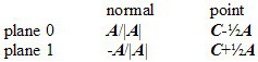
We assume that the bounding box is stored as four vectors, R , S , T and C . R , S and T are the orthogonal axes of the bounding box, with the each vector's magnitude being the size of the box along the axis. C is the center of the bounding box.
For each axis, we want to calculate the two planes for the box's end points. Let A be the axis we are currently dealing with.
Diagram 8: End point planes for axis A of bounding box.
As derived above, we can define a plane given its normal, and a point on the plane. So the two planes for an axis A are,
Given a normal convex polyhedron - bounding volume intersection test implementation, polyhedron planes that meet at an acute angle are likely to give false positives. This occurs because it is possible for an object's bounding volume to intersect the positive half space of each plane, yet still not intersect the polyhedron. Diagram 9 illustrates an example of this.
Diagram 9: Polyhedra with planes that meet at an acute angle increase occurrence of false positives.
Acute angles are much more likely to occur when generating shadow caster volumes for semi-transparent objects than for view frustums. A solution to this problem is to add an additional plane to the shadow caster volume polyhedron [LENG02a].
Diagram 10: Adding an extra plane to the polyhedron prevents the false positive.
5.0 Summary
To cull shadow casters that do not affect the visible scene, we have introduced a shadow caster volume. Only objects that intersect both the shadow caster volume and the light source's bounding volume can cast a visible shadow.
For rendering shadow receiving semi-transparent objects, we can calculate a smaller shadow caster volume that only intersects objects that can cast a shadow onto the semi-transparent object, not the entire visible scene.
Once the shadow casters have been determined by using a shadow caster volume, scissor tests and depth tests can be used to reduce the amount of work done per shadow caster [LENG02b] [LENG05] .
Listing 1 is the implementation of the shadow caster volume calculation for a point light source. Listing 2 is a Polyhedron class that includes the calculations for polyhedron vertices and edges, and listing 3 is the LUP decomposition implementation.
References
Introduction to Algorithms, 2nd Ed, (The MIT Press, 2001). ISBN 0-262-03293-7
Arithmetic. http://docs.sun.com/source/806-3568/ncg_goldberg.html
(Charles River Media, Inc., 2002). ISBN 1-58450-037-9
http://www.gamasutra.com/features/20021011/lengyel_01.htm
(GDC 2005).
http://www.gdconf.com/
http://www.terathon.com/
Numerical Recipes in C, The Art of Scientific Computing, 2nd Ed,
(Cambridge University Press, 1988). ISBN 0-521-43108-5
http://www.library.cornell.edu/nr/bookcpdf.html
Listing 1
/**
 * Gets the volume containing all objects that can cast a shadow
 * into the view frustum.
 * @param frustum view frustum
 * @return shadow caster volume
 */
Polyhedron PointLightSource::shadowCasterVolume( Polyhedronconst& frustum ) const
{
        // If lightsource lies inside frustum, then simply return frustum.
        if ( frustum.pointInside( _position ) ) {
                return frustum;
        }

        // Create a new polyhedron, using all frustum planes for which the light
        // source lies on the positive side of (or lies exactly on the plane),
        // and creating new planes for each edge that is shared by one plane that
        // points towards the light and one that points away.

        // First copy all planes pointing towards the light source
        Polyhedron shadowVol;
        Polyhedron::PlanesItors planesItors = frustum.getPlanes();
        for ( Polyhedron::PlanesItor p=planesItors.first; p!=planesItors.second; ++p )
        {
                if ( p->dist(_position) >= 0 ) {
                        shadowVol.addPlane( *p );
                }
        }

        // Calculate the average of the frustum vertices.
        // This is used for determining the direction of the
        // normals for the new planes.
        Polyhedron::VerticesItors const verticesItors = frustum.getVertices();
        Polyhedron::Vertex verticesAverage( 0.f );
        double numVertices = 0;
        for ( Polyhedron::VerticesItor v=verticesItors.first; v!=verticesItors.second; ++v )
        {
                verticesAverage += *v;
                ++numVertices;
        }
        verticesAverage /= numVertices;

        // Now add new planes for all silloute edges
        Polyhedron::EdgesItors const edgesItors = frustum.getEdges();
        for ( Polyhedron::EdgesItor e=edgesItors.first; e!=edgesItors.second; ++e )
        {
                // One plane faces light and other faces away (or is parallel) ?
                bool const p0pos = e->plane[0]->dist(_position) >= 0;
                bool const p1pos = e->plane[1]->dist(_position) >= 0;
                if ( p0pos != p1pos ) {

                        // Create new plane
                        Vector<3, double> n( (e->end[0]-_position).cross(e->end[0]-e->end[1]).norm() );
                        Plane p( n, e->end[0] );
                        // Ensure the normal is pointing in the correct direction.
                        if ( p.dist( verticesAverage ) < 0 ) {
                                p = -p;
                        }

                        // Save the plane
                        shadowVol.addPlane( p );
                }
        }

        return shadowVol;
}
Listing 2
/**
* Convex polyhedron.
*
* Note that there is no checking to enforce convexity.
*
* Polyhedron is defined as the intersection of the
* positive half-spaces for a list of planes.
* That is, plane normals must point inwards.
*
* Degenerate infinite polyhedra are supported, the
* simplest case of this being a half-space.
*/
template < class T= double >
class Polyhedron {
typedef std::vector< Plane > Planes;
public :
/**
* Constructor
*/
Polyhedron()
: _recalculateVertices( true )
, _recalculateEdges( true )
{
}
/**
* Adds a plane to polyhedron.
* @param p plane
*/
void addPlane( Plane const& p ) {
_planes.push_back( p );
_recalculateVertices = true ;
}
/// Const iterator over a collection of planes
typedef typename Planes::const_iterator PlanesItor;
/// Pair of PlanesItor's, where first is begin, and second is end.
typedef std::pair PlanesItors;
/**
* Get the begin and end const iterators over the planes.
* @return plane begin and end iterators
*/
PlanesItors getPlanes() const {
return PlanesItors( _planes.begin(), _planes.end() );
}
/**
* Test if a point lies in (or on) the polyhedron.
* @param point point
* @param error each "point" is given a radius of
* max(error, error*plane's distance to origin)
* @return true iff point lies in or on the polyhedron
*/
bool pointInside( Vector<3,T> const& point, T error=1e-3 ) const {
for ( PlanesItor i=_planes.begin(); i!=_planes.end(); ++i ) {
if ( i->dist(point) < -std::max( error, std::fabs(error*i->d()) ) )
{
return false ;
}
}
return true ;
}
private :
/// Vertex of the polyhedron
struct PlanesVertex {
PlanesItor plane[3]; ///< planes that meet at the vertex
Vector<3,T> pos; ///< vertex position
};
/// Collection of PlanesVertex's
typedef std::vector PlanesVertices;
public :
/// Vertex of the polyhedron
typedef Vector<3,T> Vertex;
private :
struct VertexCmp {
/**
* Vertex comparison operator for use in std::set.
* @param v0 first vertex
* @param v1 second vertex
* @return true iff v0 "is less than" v1
*/
bool operator ()( Vertex const & v0, Vertex const & v1 ) const {
if ( v0[0] < v1[0] ) return true ;
if ( v0[0] > v1[0] ) return false ;
if ( v0[1] < v1[1] ) return true ;
if ( v0[1] > v1[1] ) return false ;
return v0[2] < v1[2];
}
};
/// Collection of Vertex's
typedef std::set Vertices;
public :
/// Const iterator over a collection of vertices
typedef typename Vertices::const_iterator VerticesItor;
/// Pair of VerticesItor's, where first is begin, and second is end.
typedef std::pair VerticesItors;
/**
* Gets the begin and end const iterators overt the vertices
* @return vertex begin and end iterators
*/
VerticesItors getVertices() const {
if ( _recalculateVertices ) {
_recalculateVertices = false ;
_recalculateEdges = true ;
// First calculate _planesVertices
_planesVertices.clear();
for ( PlanesItor p0=_planes.begin(); p0!=_planes.end(); ++p0 ) {
PlanesItor p1 = p0;
for ( ++p1; p1!=_planes.end(); ++p1 ) {
PlanesItor p2 = p1;
for ( ++p2; p2!=_planes.end(); ++p2 ) {
// Test if the planes intersect at a point
Matrix<3,3,T> m;
Vector<3,T> const& n0( p0->n() );
Vector<3,T> const& n1( p1->n() );
Vector<3,T> const& n2( p2->n() );
m[0][0] = n0[0]; m[0][1] = n0[1]; m[0][2] = n0[2];
m[1][0] = n1[0]; m[1][1] = n1[1]; m[1][2] = n1[2];
m[2][0] = n2[0]; m[2][1] = n2[1]; m[2][2] = n2[2];
// Find the point of intersection
typename Matrix<3,3,T>::Lup const lup( m, false );
if ( !lup.failed() ) {
Vector<3,T> const d(-p0->d(),-p1->d(),-p2->d());
Vector<3,T> const pos( lup.solve(d) );
// Now check that the point is in or on
// the polyhedron
if ( pointInside( pos ) ) {
// Save the vertex
PlanesVertex const pv = { {p0,p1,p2}, pos };
_planesVertices.push_back( pv );
}
}
}
}
}
// Now calculate unique set of vertex positions
_vertices.clear();
for ( typename PlanesVertices::const_iterator pv=_planesVertices.begin(); pv!=_planesVertices.end(); ++pv )
{
_vertices.insert( Vertex(pv->pos) );
}
}
return VerticesItors( _vertices.begin(), _vertices.end() );
}
/// Edge of polyhedron
struct Edge {
PlanesItor plane[2]; ///< planes that meet to form the edge
Vector<3,T> end[2]; ///< vertex positions
};
private :
struct EdgeCmp {
/**
* Edge comparison operator for use in std::set.
* @param e0 first edge
* @param e1 second edge
* @return true iff e0 "is less than" e1
*/
bool operator ()( Edge const & e0, Edge const & e1 ) const {
for ( unsigned i=0; i<2; ++i ) {
for ( unsigned j=0; j<3; ++j ) {
if ( e0.plane->n()[j] < e1.plane->n()[j] )
return true ;
if ( e0.plane->n()[j] > e1.plane->n()[j] )
return false ;
}
if ( e0.plane->d() < e1.plane->d() ) return true ;
if ( e0.plane->d() > e1.plane->d() ) return false ;
}
for ( unsigned i=0; i<2; ++i ) {
for ( unsigned j=0; j<3; ++j ) {
if ( e0.end[j] < e1.end[j] ) return true ;
if ( e0.end[j] > e1.end[j] ) return false ;
}
}
return false ;
}
};
/// Collection of Edge's
typedef std::set Edges;
public :
/// Const iterator over collection of edges
typedef typename Edges::const_iterator EdgesItor;
/// Pair of EdgesItor's, where first is begin, and second is end.
typedef std::pair EdgesItors;
/**
* Gets the begin and end const iterators overt the edges
* @return edge begin and end iterators
*/
EdgesItors getEdges() const {
getVertices();
if ( _recalculateEdges ) {
_recalculateEdges = false ;
_edges.clear();
for ( typename PlanesVertices::const_iterator v0=_planesVertices.begin(); v0!=_planesVertices.end(); ++v0 )
{
typename PlanesVertices::const_iterator v1 = v0;
for ( ++v1; v1!=_planesVertices.end(); ++v1 ) {
// Check that the two vertices are not the same point
// (which will happen if more than three planes meet
// at the same point)
if ( v0->pos != v1->pos ) {
// For every common pair of planes, add an edge
#define _POLYHEDRON_CMP_PLANE(n) \
( v0->plane[n] == v1->plane[0] || \
v0->plane[n] == v1->plane[1] || \
v0->plane[n] == v1->plane[2] )
#define _POLYHEDRON_ADD_EDGE(i,j) \
do { \
Edge const e = { { v0->plane, \
v0->plane[j] }, \
{ v0->pos, v1->pos } }; \
_edges.insert( e ); \
} while (0)
if ( _POLYHEDRON_CMP_PLANE(0) ) {
if ( _POLYHEDRON_CMP_PLANE(1) ) {
_POLYHEDRON_ADD_EDGE(0,1);
}
else if ( _POLYHEDRON_CMP_PLANE(2) ) {
_POLYHEDRON_ADD_EDGE(0,2);
}
}
else if ( _POLYHEDRON_CMP_PLANE(1) ) {
if ( _POLYHEDRON_CMP_PLANE(2) ) {
_POLYHEDRON_ADD_EDGE(1,2);
}
}
#undef _POLYHEDRON_ADD_EDGE
#undef _POLYHEDRON_CMP_PLANE
}
}
}
}
return EdgesItors( _edges.begin(), _edges.end() );
}
private :
Planes _planes;
mutable bool _recalculateVertices;
mutable PlanesVertices _planesVertices;
mutable Vertices _vertices;
mutable bool _recalculateEdges;
mutable Edges _edges;
};
Listing 3
/**
 * LUP decomposition of a matrix.
 * For a matrix non-singular square matrix M, it's decomposition satisfies
 * PM = LU
 */
template < int ROWS, int COLS, class T >
class Matrix::Lup {
BOOST_STATIC_ASSERT( ROWS == COLS );

public :

        /**
         * Constructor
         * @param m matrix to decompose
         * @param canThrow if set, MatrixSingularException will be thrown if
         * LUP decomposition fails (the default), otherwise,
         * use the failed() method to test whether or not
         * the decomposition was successful
         */
        explicit Lup( Matrix const & m, bool canThrow= true )
        : _failed( true )
        , _lu( m )
        {
                // This is an implementation of the LUP-DECOMPOSITION algorithm
                // presented in Cohen, Leiserson, Rivest and Stein. "Introduction To
                // Algorithms", 2nd Ed. MIT Press. 2001.

                // Initialise _p to identity transform
                for ( unsigned i=0; i = i;
                }

                // Loop through each column
                // While the last iteration does not modify the matrix _lu in anyway,
                // it is required to check for singularity.
                for ( int k=0; k// Find the row with the largest absolute value element